용도에 의한 분류
- 생물현미경
- 금속현미경
- 측정현미경
- 실체현미경
형태에 의한 분류
- 정립형 현미경
- 도립형 현미경
기능에 의한 분류
- 명시야 현미경
- 암시야 현미경
- 편광 현미경
- 미분간섭 현미경
- 위상차 현미경
- 형광 현미경
- 공초점 현미경
그외 현미경
- 적외선 현미경
- 자외선 현미경
- X선 현미경
- 전자현미경
- 원자 현미경

이 사이트는 현미경에 대한 궁금증을 해결하는데 있어서, 도움이 되고자 하는 교육 목적으로 준비하고 있는 사이트입니다만, 현업에서의 경험을 포함하는 상업 사이트로서의 성격도 포함하고 있습니다.
Site 관리자 – 진재환 올림
E-mail : jhjin@jnoptic.com

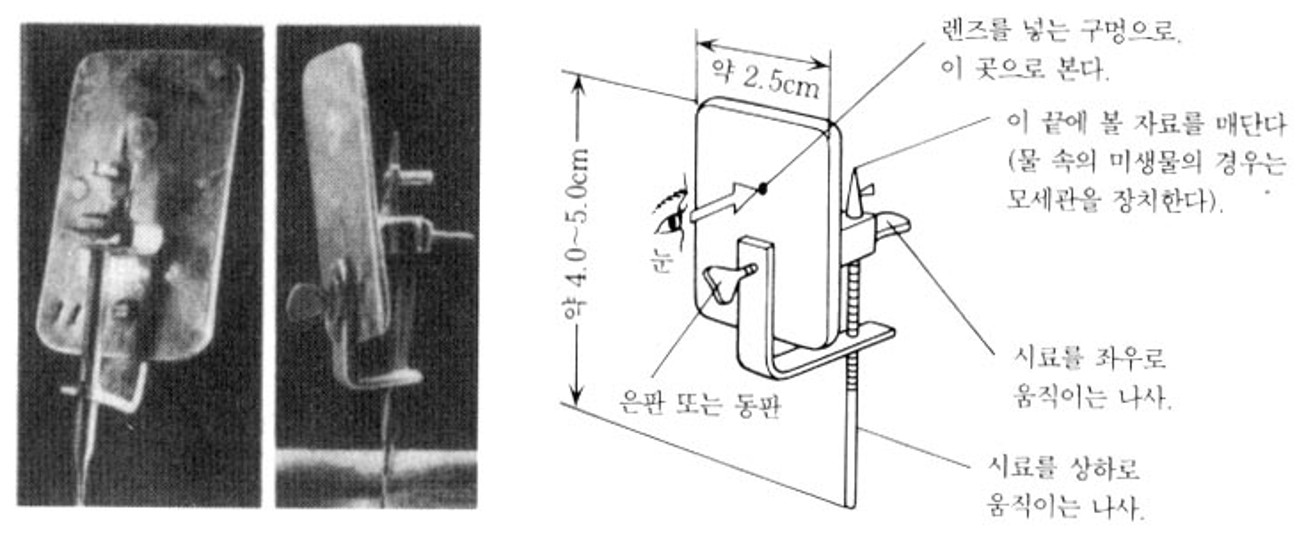
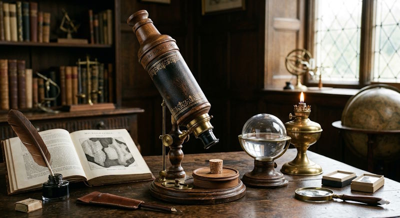
가시광선을 주로 사용하는 광학 현미경은 상기와 같이 단렌즈 현미경으로 시작하여 대물렌즈와 접안렌즈를 조합하여 사용하는 복합현미경의 모습으로 기본 구조를 갖추어 왔습니다. 또한 보다 높은 배율을 추구할 수록 흐려지는 이미지의 질을 높이기 위한, 수 많은 시도의 결과로 현재 우리는 양질의 이미지를 볼 수 있는 현미경을 사용할 수 있습니다.
또한 일반인이 흔히 알고 있는 광학현미경은 Bright Fileld 라고 불리는 관찰법으로써 설명 할 수 있습니다. 하지만, 이 관찰법만으로는 다양한 샘플을 보고자 하는 탐구자들의 욕구를 만족시키기 어렵기 때문에, 보다 다양한 관찰 방법이 개발되어 왔고, 향후에도 새로운 관찰법이 끊임없이 개발될 것으로 기대됩니다.
참고로, 오늘날의 대표적인 현미경 관찰법을 열거하자면 BF, DF, PO, Simple PO, DIC, PH, FLUORESCENCE 등을 들수 있습니다.
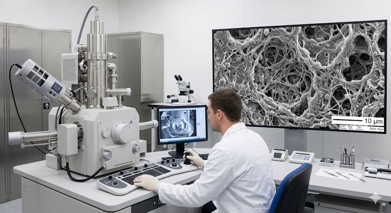
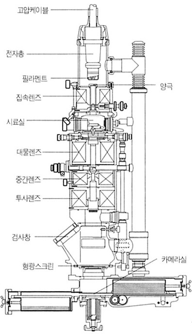
원자 현미경은 원자를 관찰할 수 있다는 의미에서 이름이 붙여졌습니다. 원자 현미경의 원리는 원자 표면을 뾰족한 탐침으로 긁어서 원자를 지날 때 탐침이 움직이면 레이저가 그것을 포착하여 원자의 모습을 파악하게 되는 것입니다.
원자 현미경에는 주사 탐침 현미경(Scanning Probe Microscope; SPM)과 원자힘 현미경(Atomic Force Microscope; AFM) 등이 있습니다. SPM은 시료와 탐침 양쪽에 전기를 걸어 양자역학적 터널링 현상으로 전류가 흐르는 특성을 이용한다. 전류를 일정하게 유지하고 탐침을 시료 위에서 움직이면 탐침의 움직임을 컴퓨터로 분석해 시료 표면의 원자 구조 이미지를 그려 내는 것이다. AFM은 시료가 전기를 통하지 않는 물질일 때 사용하는데, 시료와 탐침 원자 사이에 작용하는 힘을 이용하여 시료의 형상을 측정합니다. AFM은 SPM보다 표면을 그려 내는 최대 해상도는 부족하지만 시료를 거의 손상시키지 않는다는 장점이 있습니다.
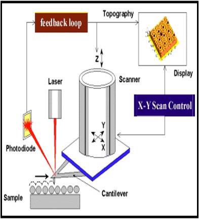
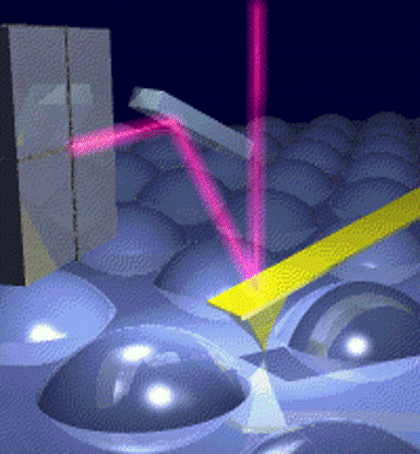
이미지 상단부분을 클릭하시면 원본 이미지를 확인하실 수 있습니다.


압착률 측정 프로그램입니다.
< 압착율, 압착고, 압착폭, 공극율 자동측정 >
| 먼저 관찰이 용이하게 하기 위해 전선 단면은 깔끔하게 절단 또는 폴리싱장비를 사용하여 시료 준비를 합니다. 심선 스펙상의 지름과 선 개수를 먼저 입력을 한후 압착 부분을 선택 하게 되면 #압착률 이 자동계산되어 나타납니다 |

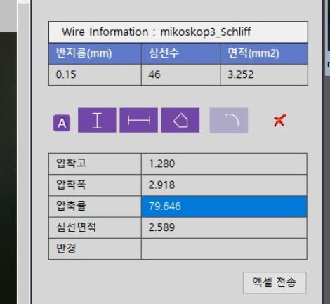


자동 측정 및 데이터 분석, 데이터 보고서 생성 등의 모듈이 포함됩니다. 단자의 단면 분석을 완료하기 까지 5분이면 충분합니다.
기공율(공극율) 분석 프로그램 JNO-IX
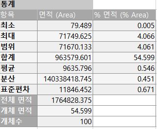
기공률분석, 공극률 분석, Particle Analysis, Porosity Analysis
다공성재료에서 비어있는 부분이 차지하는 비율을 자동으로 계산합니다
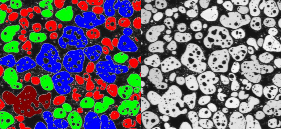
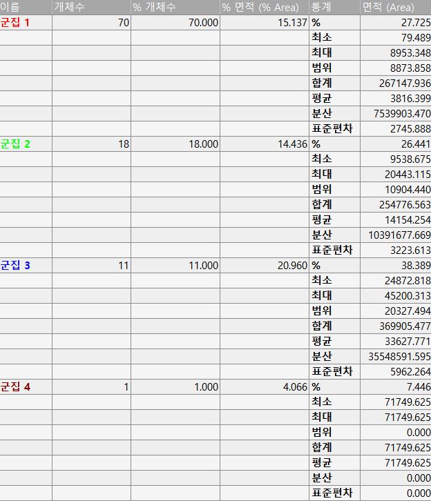
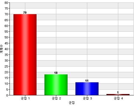
모든 기공의 면적을 측정하여 일정 구간에 대한 통계를 자동으로 산출
샘플 이미지를 보내주시면 테스트 가능합니다. jhjin@jnoptic.com
자세한 문의 사항은 02-3473-4188
관찰하는 샘플의 전체 Field of View에서 밝고 균일 한 조명을 구현하기 위해서 사용되는 일반적인 조명 방법입니다. ( Köhler illumination )
조명 광원이 광학계의 내부에서 결상을 하게 되어 있습니다. 예전에 사용되었던 크리티컬 조명에서는 샘플의 상에 조명광원의 필라멘트 상이 겹쳐서 보이게 됩니다만, 쾰러 조명은 조명의 결상 위치를 무한보정 대물렌즈의 후초점면에 위치하도록 유도함으로서 샘플의 상에 광원의 상이 중복되는 문제점을 해결 하면서, 동시에 샘플 전체에 균일한 조명을 조사하는 것이 가능해 졌습니다.
현미경의 모든 관찰법은 상기와 같은 쾰러 조명을 기반으로 설계되어 있습니다. 따라서 쾰러 조명의 세팅 또는 설정이 틀어져 있는 상태에서의 현미경의 관찰은 그 설계 목적을 완전히 벗어나 있는 현미경 관찰을 하게 되는 것이며, 사용중이라고 생각하는 본래의 관찰법과는 상이한 알 수 없는 관찰법으로 샘플을 관찰 하는 비효율적인 경우가 빈번하게 발생되고 있습니다.
쾰러 조명에 대한 명칭을 생소하시게 느껴지신다면, 독자께서는 지금까지 현미경의 중요한 포인트를 제대로 알지 못하고 사용하시고 계셨을 가능성이 있습니다. 바이오 이미징을 하시는 관찰자께서는 사용하시는 현미경의 쾰러 조명 설정이 제대로 되어있는지 반드시 확인하실 필요가 있습니다.
다만, 반사용 현미경을 주로 사용하시는 산업계 현미경 사용자 분들은 이러한 쾰러 조명의 잘못된 설정으로 받는 영향이 상대적으로는 적습니다. 그 이유로는 반사관찰을 위주로 하는 현미경에서는 대물렌즈 자체가 콘덴서 역할을 하기 때문에 쾰러 조명을 설정하기 위해서 콘덴서 위치 교정이 따로 필요하기 않기 때문입니다.
반사형 조명을 사용하는 현미경에서는 샘플에 초점을 맞추면, 그 자체로 콘덴서의 높이 설정이 완료되고 ( X, Y, Z축 위치 설정 ), Field 조리개(diaphragm)와 Aperture 조리개(diaphragm)의 설정(XY축 교정)이 상대적으로 변경되기 어려운 구조를 가지고 있기 때문에 입니다.
KÖHLER ILLUMINATION은 현미경 광 경로 상에 2개의 결상계가 서로 결상 되지 않는 영역을 상보적으로 사용하도록 설계되어 있다.
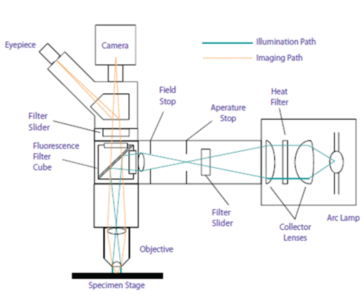
첫째로는 샘플의 상이 형성되는 이미징용 결상계
두번째로는 조명 광원의 상이 형성되는 결상계

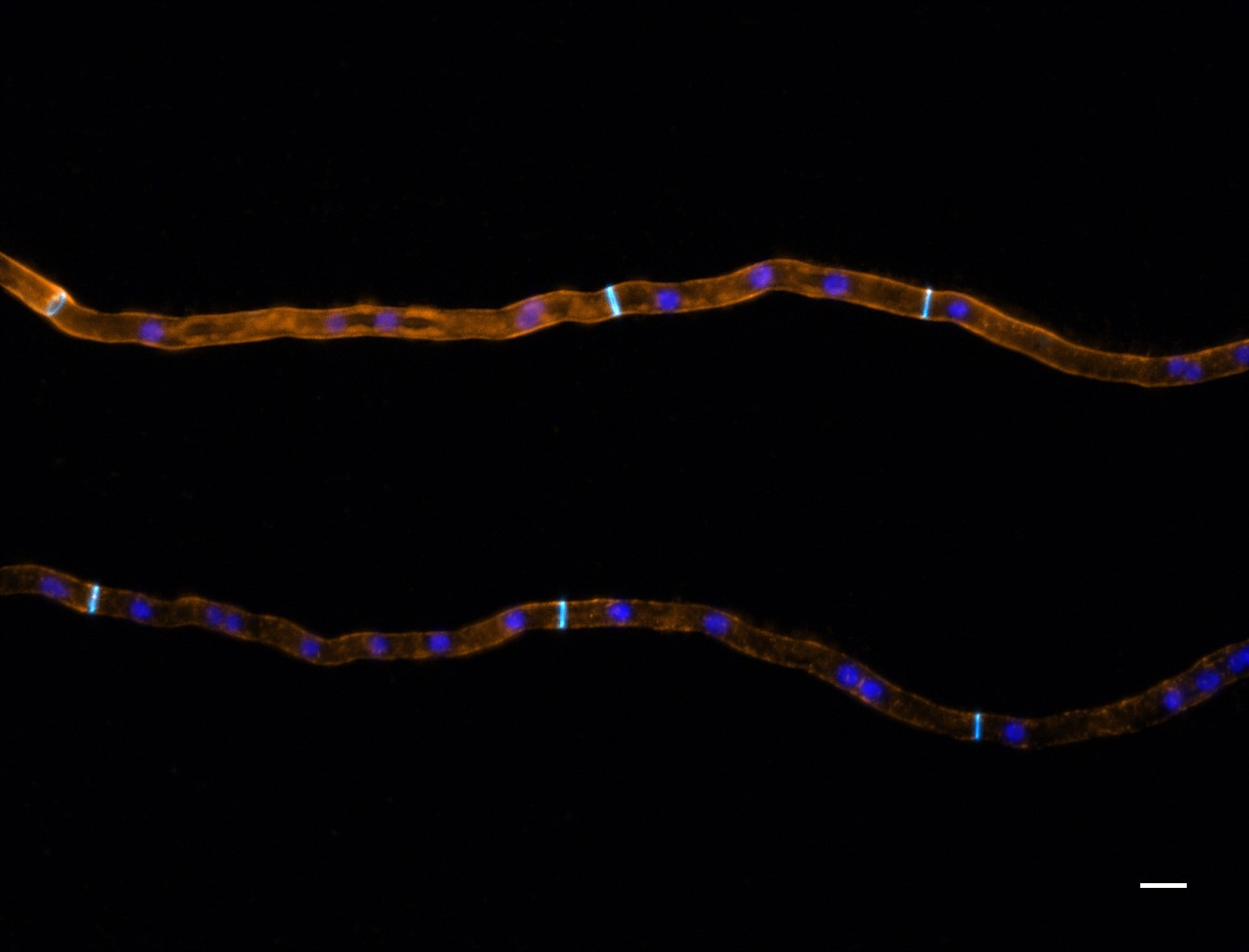
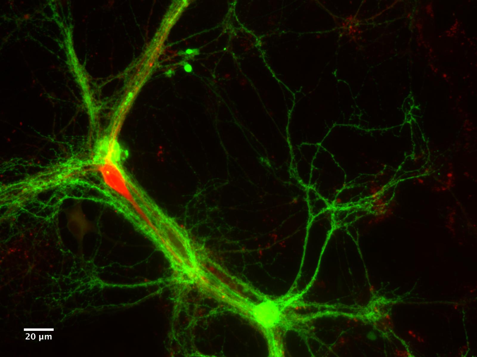
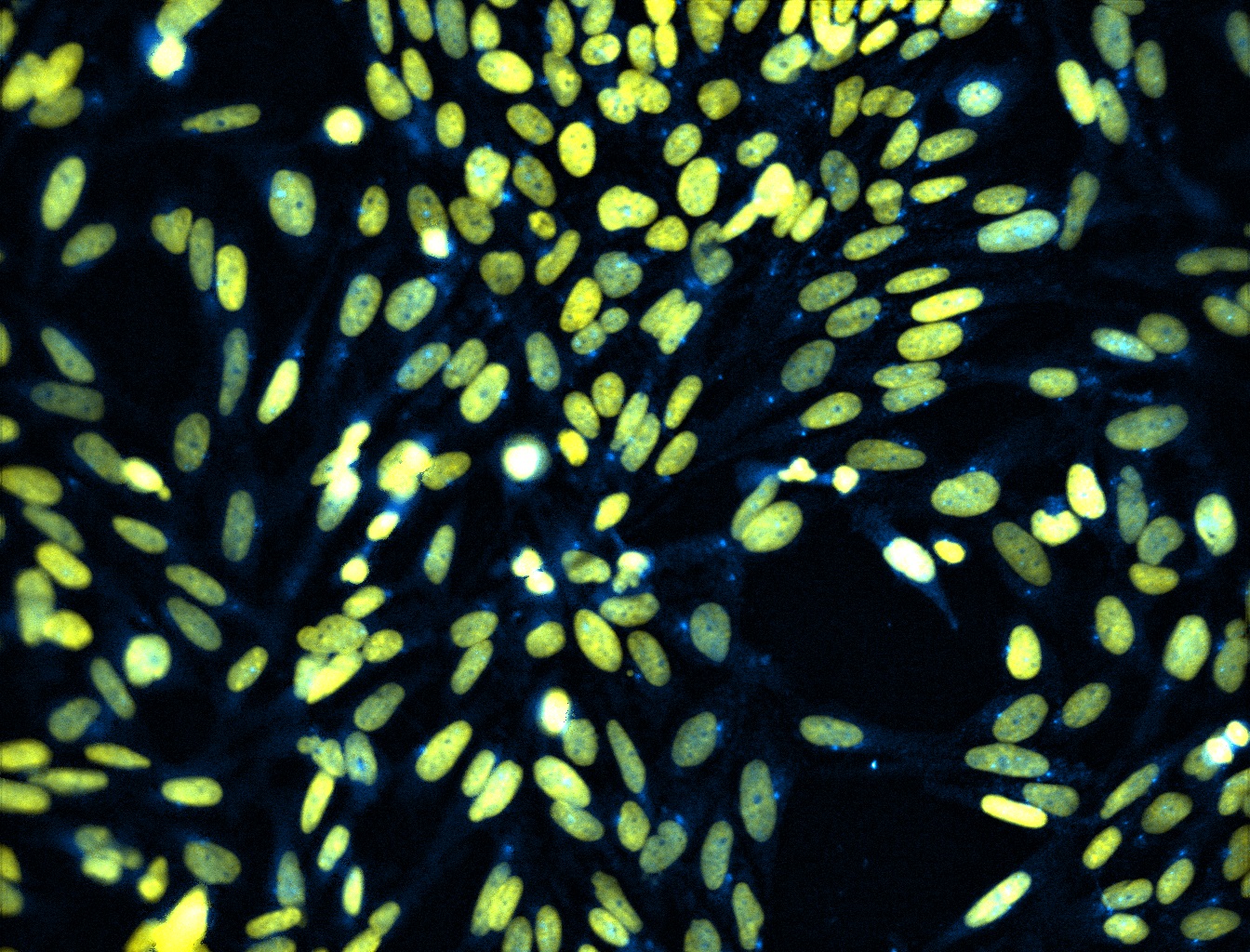
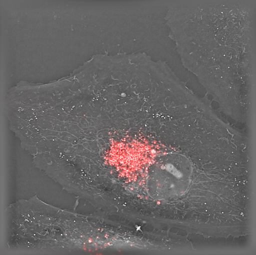


pE-300 Series
CoolLED pE-300 Series Datasheet
CoolLED pE-300lite Exploded Diagram
CoolLED pE-300white Exploded Diagram
CoolLED pE-300ultra Exploded Diagram
CoolLED pE-300ultra Optogenetics Leaflet
CoolLED pE-300 Series User Manual
CoolLED pE-300 Series Quick Start Guide
CoolLED pE-300 Series Troubleshooting Guide
CoolLED Driver File
CoolLED pE-300 Series Essential Commands Manual
CoolLED pE-Exerciser
CoolLED Firmware Update Program
CoolLED pE-300 Series Firmware Update Instructions
pE-340fura
CoolLED pE-340fura Datasheet
CoolLED pE-340fura Exploded Diagram
CoolLED pE-340fura User Manual
CoolLED pE-340 Quick Start Guide
CoolLED pE-340fura Troubleshooting Guide
CoolLED pE-340fura Essential Commands Manual
pE-4000
CoolLED pE-4000 User Manual
CoolLED pE-4000 Quick Start Guide
CoolLED pE-4000 Troubleshooting Guide
CoolLED pE-4000 leaflet
CoolLED pE-4000 Exploded Diagram
CoolLED Driver File
CoolLED pE-4000 Essential Commands Manual
CoolLED pE-Exerciser
CoolLED Firmware Update Program
CoolLED pE-4000 Firmware Update Instructions
| Company | Software | Summary | Screenshot | Quick Start |
|---|---|---|---|---|
| Andor | Andor iQ | Click Here | Click Here | Click Here |
| Hamamatsu | HCImage | Click Here | Click Here | Click Here |
| LaVision BioTec | ImSpector Pro | Click Here | Click Here | |
| Leica | LASX | Click Here | Click Here | Click Here |
| Micromanager | Micromanager | Click Here | Click Here | Click Here |
| Molecular Devices | MetaMorph | Click Here | Click Here | Click Here |
| Nikon | NIS Elements | Click Here | Click Here | Click Here |
| Olympus | CellSens | Click Here | Click Here | Click Here |
| Visitron Systems | Visiview | Click Here | Click Here | |
| Intelligent Imaging Innovations (3i) | Slidebook | Click Here | Click Here | Click Here |
| Zeiss | ZEN | Click Here | Click Here |
The pE-100 system has been developed for fluorescence applications requiring a single LED excitation wavelength. It is perfect for clinical applications such as routine screening (e.g. using Auramine for Tuberculosis), for research applications requiring precise intensity control and fast-switching, or for electrophysiology applications where light has to be delivered to a specific location. The user can select from 20 different LED wavelengths, ranging from the near-UV at 365nm to the near-IR at 770nm. The system comprises a pE-100 LED Light Source, control pod, and power supply.
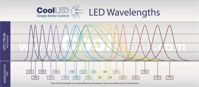
There are three standard pE-100 configuration options:
Direct-fit
(pE-100) for connecting to a microscope (epi-port) by selecting from a range of microscope adaptors which covers all current and most older models. A simple once only adjustment will allow optimisation to the optical path of the microscope.
Liquid Light Guide
(pE-100light guide) with a fixed 3mm diameter, liquid light guideFiber
(pE-100fiber) with an SMA connection for accepting multimode fibers. The pE-100fiber has been designed with efficient coupling into a wide range of multimode fibers. The pE-100fiber also includes excitation filter holders.
Combining pE-100s:
Direct fit configuration
pE-100 units can be combined using the pE-Combiner for applications requiring a second LED wavelength with independent control and triggering.
Liquid light guide or multimode fiberusing a fixed two wavelength configuration can be specified. Two pE-100 Light Sources are combined, providing independent control and triggering. For further information go to the Downloads tab